We may earn revenue from the products available on this page and participate in affiliate programs. Learn more ›
A myriad of electrical gremlins can come to light with a car’s age—bad terminals, broken wires, blown fuses, and even fried relays. Knowing how to diagnose those problems can be the difference between staring hopelessly under your hood while uttering some choice four-letter words and actually fixing the problem.
Cars aren’t getting any less complex, either. Most newer cars today have some sort of electrical component or computerized device behind just about everything. Components that require high currents often use relays to switch the circuits, and being that a relay has moving parts, they can eventually go bad. And when they do, they can be a real head-scratcher.
So buckle up, because your good friends at The Drive are going to teach you how to test these tiny electronic switches


Safety First
Working on your car can be dangerous. There are fans, belts, and plenty of things that can zap or cut you. Always take proper precautions when working on your own car and remember that electricity can be dangerous.
Here are a few basic tips to remember:
- Electricity can shock you! Always take proper precautions when working with electricity.
- Don’t work in an environment with flammable liquids or gasses. Electricity can produce sparks, which could ignite combustible material.
- Refer to your vehicle’s safety manual and a reputable repair manual before working on your car. We can give you tips, but an official resource should be gospel for both tech and safety.
Everything You’ll Need To Test a Relay

Testing a relay is a fairly simple process that you can do at home with very little equipment. In a pinch, you can use your car’s battery and a multimeter, but to perform some proper bench testing, you can use a proper setup with a desktop power supply. Here’s a complete list of parts you will need to test your own relay.
Tools and Parts
- Benchtop power supply
- Multimeter
- Alligator clips
- Test leads
- Test Relay (if you want to try the process on a new part that isn’t from your car)
Here’s How to Test a Relay, Step by Step
Step 1: Understanding How a Relay Works

Before we get into how to test a relay, we should understand how it works. There are multiple types of relays, but in this guide, we’ll focus on the operation of a typical four-pin relay that is configured as a normally open Single-Pole Single-Throw (SPST).
These relays consist of four pins typically labeled 85, 86, 87, and 30. Pins 85 and 86, located across from one another, are for the electromagnetic coil. Pins 87 and 30 are for the switched circuit. When you energize the electromagnetic coil circuit, it closes a switch between pins 87 and 30 and allows power to pass through the relay and to whatever is powered on the other side (for example, your headlights or a cooling fan).
The actual DIN 72552 standard defines each pin as follows:
- 30: From battery +
- 85: Relay coil –
- 86: Relay coil +
- 87: Common contact
- 87a: Normally-closed contact
- 87b: Normally-open contact
Step 2: Locate the Relay
So you’ve scoured the internet and determined that you need to test a relay. Well, the next step is actually finding that relay, and depending on what it controls, it could be just about anywhere—under the hood, in the fuse box, under the dash, or elsewhere. We recommend consulting a vehicle-specific repair manual to determine the location. It may also be found in a wiring diagram of your vehicle.
Step 3: Swap Out the Relay
The easiest way to test a relay is to simply swap it out with a known-good part. Relays are often cheap, but having one on hand isn’t always going to happen. Watch out, though—whatever it was that cooked your first relay can do exactly that to your second one if the root of the problem isn’t fixed.
Step 4: Measure the Resistance
It’s time to break out your multimeter. You can prepare to test your relay in the car, or put it on a test bench like us. Either way, be sure to de-energize your relay by removing power to it before you get to work.
Next, you’ll set your multimeter to measure resistance by switching it to read ohms. You will want to measure the resistance between your electromagnetic coils, which is a Normally Closed (NC) circuit. On a four or five-pin relay, these are pins 85 and 86.
If you get a measurement between 50 and 120 ohms, the coil is likely good. Anything out-of-spec means that the coil winding is bad and you’ll need a new relay.
Step 5: Test Switch Pin Continuity
Now that we know that your coil is good, we’ll want to test the switch pins. These pins are a Normally Open (NO) circuit, meaning that they are open by default and have no continuity. There should be no load traveling through it until the circuit is closed by energizing the relay.
To test this, leave your multimeter on the ohms setting and measure the resistance between the switch pins. On a four-pin relay, these are typically labeled 87 and 30. You should see no resistance at all between these pins. If you do, that means that the pins are stuck closed and the relay is bad.
Step 6: Test the Energized Relay
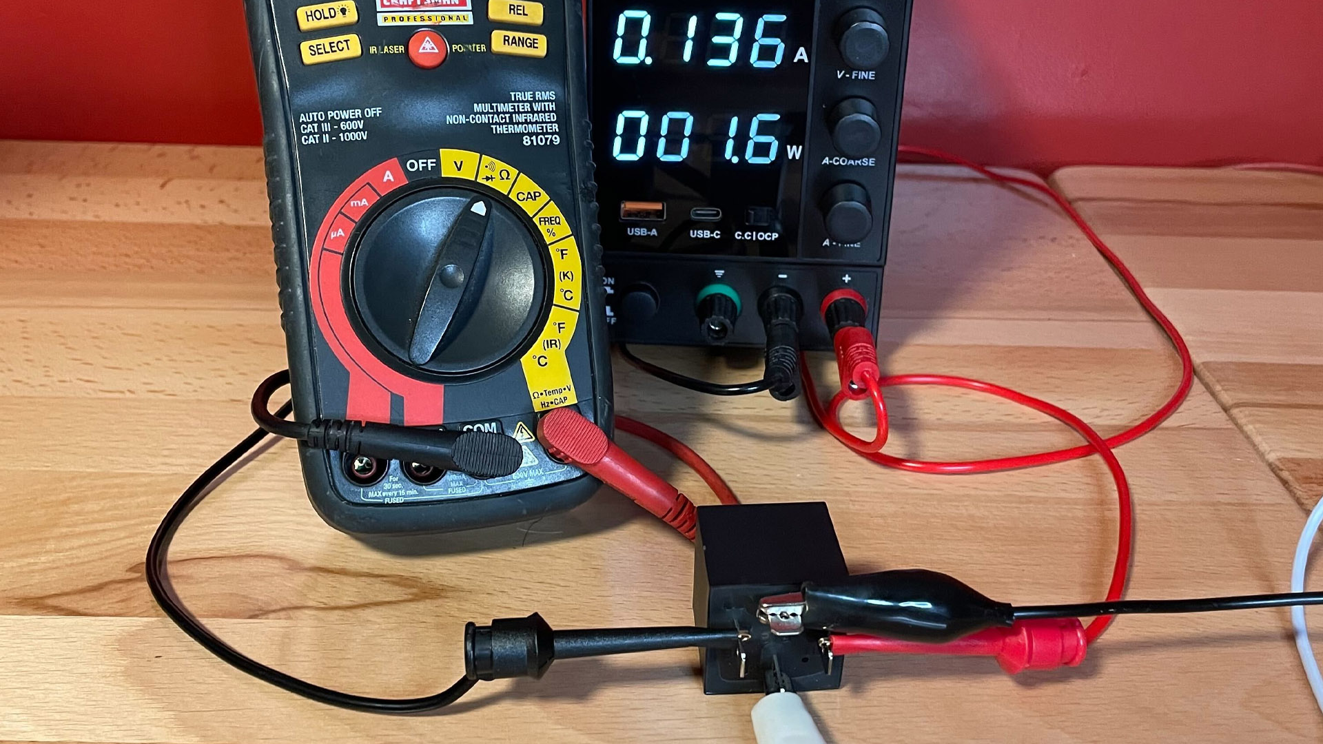
Since we’ve verified that your relay is in working order when not powered, it’s time to see what happens when we add a bit of electricity to the mix. We’re going to be using a simple benchtop power supply to test our relay, but you can use a 9-volt battery or the 12-volt power coming from your car.
Energize the coil pins (again, these are typically 85 and 86 on a 4-pin relay). You should hear an audible click as the electromagnetic coil is energized and the internal switch closes.

You will now set your multimeter on its continuity setting. This setting typically gives an audible beep when a circuit has continuity, and because you’re handling an energized circuit, it’s easier to keep your eyes on the relay and your ears listening for the beep.
Since you energized the coil pins, the NO circuit between the switch pins (87 and 30 on a four-pin relay) is now closed. You can take each probe on the multimeter and touch either corresponding switch pins and you should hear a beep to indicate continuity between the pins.
If you don’t hear a beep, your switch pins are stuck open and the relay is bad.

Step 7: Test the Voltage
Just because your relay’s switching function works doesn’t mean that it’s good. You’ll still want to test that your relay is delivering the correct voltage on the switched end to account for corroded or bad contact points.
Set your multimeter to DC volts and ensure you know the supply voltage. If using a benchtop power supply, you should see this on the power supply itself. If using your car’s battery, measure the voltage across the terminals. A non-running car’s battery should measure very close to 12 volts.

Next, with your relay energized and power supplied to one side of the switch pins, measure the voltage on the switch pin without any wires going to it. This should read close, if not identical, to the supply voltage. If it doesn’t, replace the relay.
Congratulations—you’re done!
Video
How To Test a Relay The Easy Way
If you’ve never tested a relay before, it might seem like a difficult task. Our pictures help, sure, but sometimes seeing it on video helps even more. The above clip is a great resource to use when measuring your first four-pin relay.